From this post you will learn more about the ConnectorIO's software platform architecture.
The 4 Layers of every Building Automation System
Every Building Automation System or BAS consists of four layers:
- Server/Application Layer
- Supervisory Layer
- Field Controller Layer
- Input/Output Layer
Here's how we approach this structure in ConnectorIO.
Platform's architecture
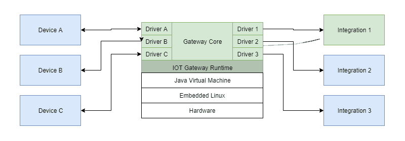
The image above shows a few important elements - multiple devices and multiple integrations.
The devices are blue because they come from 3rd party vendors. We do not plan to ship our own hardware for sensors, switches or dimmers. What we are focused on are software-based controllers and/or receivers.
Most of the integrations are also marked with blue color because the platform is able to send or receive data from anywhere, not only to or from its own vendor’s equipment.
Diagram

ConnectorIO's software architecture (simplified)
How to read this diagram?
- All external components, which are not the main point of interest, are marked with blue color. This includes 3rd party devices, external software, and other integrations.
- Internal components, which are a point of interest, and which are going to be developed and/or maintained, are marked with green color.
Top-Down Platform Structure
Here's a look at the ConnectorIO's Platform architecture - 3D diagrams.
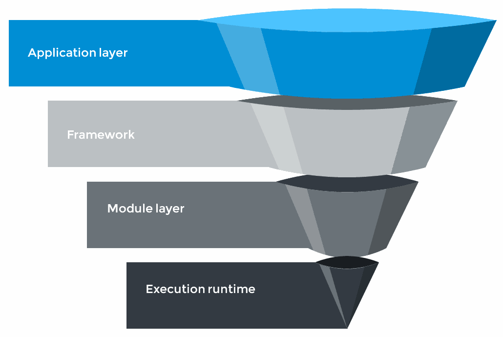
What Users see - The Application Layer
Visualization and management UI as well as standard and per customer specific extensions which build the desired value.
System's Real Power - The Framework
The framework defines standard interfaces for plug-ins and required protocol of communication.
Foundation - The Module Layer
On-demand installation of new versions of integrations and life-cycle management. Allows code hot-swap without system shutdown.
Portable Environment - Execution Runtime
Based on Java Virtual Machine works on multiple processor architectures and operating systems. From IoT Gateway up to backend server.

ConnectorIO Software top-down structure
Software Layers
Organization and abstraction.
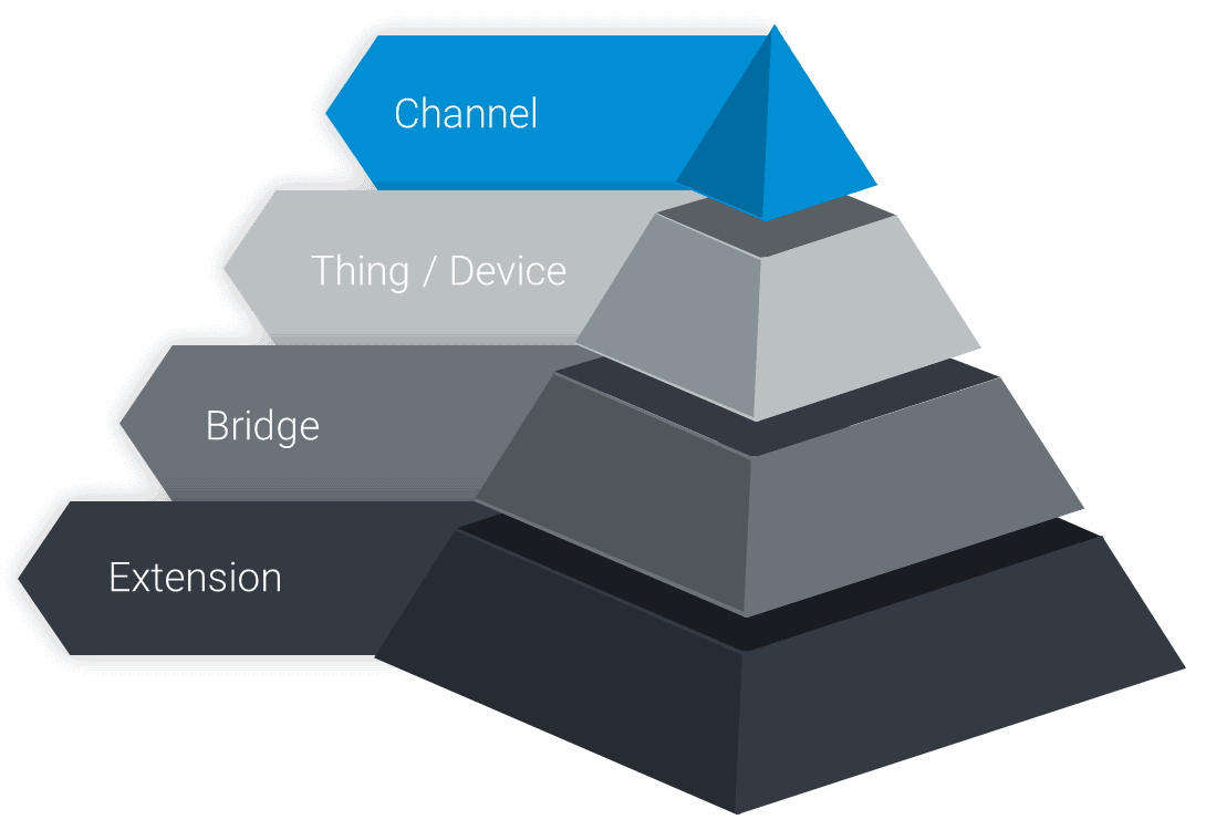
Channel: Highest and Smallest
Communication pipeline between the device and system which map a single measure or action.
Device: Aggregation
A static or dynamic set of channels and events. Might be a physical or completely virtual. For example cloud integration with the weather forecast.
Bridge: A Connection
Connection with a physical system which allows to group devices and tracks their availability together.
Extension: Installation Unit
Brings necessary code which handles Bridges, Devices and Channels – communication between them and the real world.

ConnectorIO Software - Local organization chart
What can be manged?
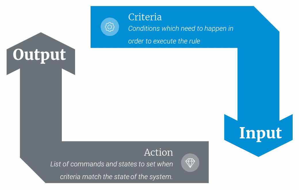
INPUTS and OUTPUTS can be managed in ConnectorIO by applying rules to them. First you need to define some Criteria - conditions which need to happen in order to execute the rule. Nest you define Actions - list of commands and states to set when the defined criteria match the state of the system.

ConnectorIO's software platform - The Rule Engine
What can be triggered?
A certain threshold, an event or state change are the most common reasons for writing a rule.For example – temperature above 22C or below 19C, sunrise, a detected motion.
What can happen?
A result of rule execution might be a state change of another channel in another device, another event. An action might include switching on the light, changing setpoint or sending an email/text message.
